At least two different optical techniques can be applied to measure the concentration of particulates – light absorption and light scattering. Light absorption is frequently used in high-concentration industrial processes, but it has some applications also in ambient air, for example to determine visibility at airports. Light scattering is utilized both in industrial and ambient applications, although then usually utilizing different types of scattering processes.
Transmission-based Monitoring
Transmission-based monitors makes use of attenuation of light. In its basic form applied to industrial processes, a beam of light is sent out from a light source mounted on one side of the duct and the light is picked up by a detector in a receiver on the opposite side of the duct. The more dust particles in the flue gas inside the duct, the more light is absorbed or scattered along the beam and the less light is picked up by the detector. The signal from the detector can then be converted and calibrated to represent the dust concentration in the duct.
A variation of this approach is a reflector placed on the opposite side of the light source, leading the light back to where it came from. The detector can then be placed in the same enclosure as the light source, thereby locating all potentially delicate optics and electronics in the same unit. The design also doubles the length of the path travelled by the light, allowing better accuracy at low dust concentrations.
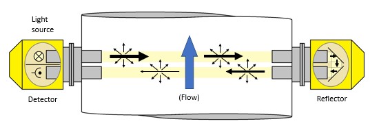
A transmission dust monitor mounted on a duct, here in a reflector-based design.
The same transmission-based principle can also be used for some ambient air monitoring, but then mainly to detect visibility. This may be of interest at for example airports.
Light-scattering Methods
Light-scattering-based monitors utilize the scattered part of the light. There is still a beam of light, but the detector now looks at the beam from the side. The higher detector signal, the higher dust concentration.
In high-concentration industrial applications such as inside ducts, it can be sufficient to just send out white light and look for the share of light which is scattered by reflection in the dense particle concentrations. However, there’s also a more subtle way of utilizing scattered light and then actually detect and establish the size of individual particles in ambient air – particle counters.
Particle Counters
In particle counter-based instruments, a steady and controlled flow of air is drawn through an inlet head, but unlike most heads for filter sampling, the inlet head allows all particle fractions to pass. The air then passes a detection chamber where light from a laser diode is focused by a lens. Light passing through the focal point is absorbed in a light trap. Particles passing close enough to the focal point will absorb the light and scatter it in random directions. This is called Mie scattering. Some of the scattered light is picked up by one or more light detectors surrounding the chamber.
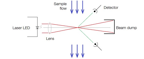
The operating principle of a particle counter based on Mie scattering.
When a particle passes the focal point, there will be a flash of light. This is detected and used to count individual particles. Further, the intensity of flash will depend on the size of the particle – the larger particle the brighter flash. These two signals, the count and the intensity, are then aggregated for all particles passing the focal point during a set period of time. The result is a statistical image of the particles in the air – a frequency diagram. Particles will also pass the light beam outside of the focal point, but they do not give rise to the intense Mie scattering and are not seen by the detectors.
It requires some assumptions and some math to go from the frequency diagram to an actual particulate concentration. In short, it’s a matter of integrating over the frequency diagram from zero up to the desired particulate fraction, multiply that with a calibration factor, and then divide by the volume that passed through the detection chamber during the monitoring time.
The monitoring times can be rather short, down to in the range of a minute, and concentration data can therefore be provided in close to real time. Additionally, a single instrument can report concentrations of two or more particulate fractions simultaneously by ending the integration at different particle sizes.
Drawbacks
The optical methods are contactless but may depend on particle sizes, density, and surface reflectivity. Applied to industrial processes, it means that changes to fuel type, combustion process, load, and dust filtering may interfere with the measurement results. In both industrial and ambient applications, water droplets are also a major interferent and the methods therefore work best in dry conditions. Notably for ambient air applications, there is also no samples preserved for e.g. metal analysis.
The triboelectric monitoring method is addressed in another blog post – click here to continue reading >>
About the Author
Bengt Löfstedt
Operative Support, OPSIS AB